Multiple customer points
Provide connected vacuum positions within the planned interior-cleaning area.
What to checkBay layout, hose reach and expected simultaneous use.

One central vacuum system
serving several bays.
Connect customer vacuum points to one central pipe network. Select the equipment around simultaneous use, required suction, pipeline layout and space for maintenance.
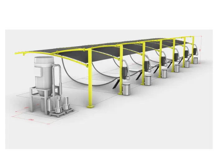
Coordinate the service points, pipe network and central unit as one system.
Provide connected vacuum positions within the planned interior-cleaning area.
What to checkBay layout, hose reach and expected simultaneous use.
Pipes run from each service point back to the central unit.
What to checkPipe length, diameter, bends and connection details.
Keep the main vacuum and filtration equipment organized for routine access.
What to checkEquipment space, dust handling, filter service and electrical supply.
Use the original system illustration to review customer stations, pipework, separation and filtration.
Original process illustration showing vacuum stations, central piping, dust and air separation, filtration and the central vacuum unit.
SHINEWASH vacuum-area installation references. Review station spacing, customer access and vehicle routes for your own site.
Customer hose positions and overhead supports alongside the vehicle area.
Another installation reference for reviewing station placement and circulation.
Published reference configurations. Start with the number of vacuum points used at the same time; the pipe network decides the final performance.
Select a model name to add it to your enquiry.
| Model | Blower type | Power | Airflow (m³/h) | Vacuum (kPa) | Simultaneous points | Weight (kg) | Noise dB(A) | Dimensions (mm) |
|---|---|---|---|---|---|---|---|---|
| AirVac-125M | Centrifugal | 12.5 kW | 1,110 | −30 | 10–12 | 540 | 76 | 2,500 × 1,500 × 3,100 |
| AirVac-200M | Centrifugal | 20 kW | 2,050 | −25 | 12–18 | 680 | 78 | 2,500 × 1,500 × 3,100 |
| AirVac-250M | Centrifugal | 25 kW | 2,050 | −31 | 12–18 | 880 | 78 | 2,500 × 1,500 × 3,100 |
| AirVac-125D | Dual centrifugal | 12.5 kW × 2 | 2,220 | −30 | 20–24 | 1,100 | 78 | 2,500 × 1,500 × 3,100 |
| AirVac-200D | Dual centrifugal | 20 kW × 2 | 4,000 | −31 | 30–36 | 1,500 | 78 | 2,500 × 1,500 × 3,100 |
| AirVac-450M | Multi-stage centrifugal | 45 kW | 3,800 | −30 | 30–36 | 2,900 | 78 | 2,500 × 1,500 × 3,100 |
Published supply reference: 380 V / 50 Hz. Point counts and system ratings are configuration references; suction at each hose depends on the pipe network. Check the installed equipment, final layout, electrical demand and local supply before ordering.
Give the equipment team the information needed to size and arrange the central vacuum system.
| Customer area | Vehicle bays, hose positions and access routes |
|---|---|
| Simultaneous use | Active points expected during the busiest period |
| Pipeline layout | Length, branches, bends and proposed pipe routes |
| Required performance | Agree suction requirements at the customer service points |
| Central unit space | Equipment footprint, ventilation and maintenance access |
| Electrical supply | Confirm the selected model and local supply requirements |
| Dust & filters | Access for collection, cleaning and routine servicing |
| Supplied scope | Central unit, pipework, stations, hoses, controls and installation responsibilities |
Answers about model selection, active points, pipework and maintenance.
Multiple customer vacuum points connect through pipework to centralized vacuum, filtration and dust-collection equipment. The central equipment serves the customer positions while concentrating routine equipment servicing in one location.
The published AirVac configurations range from 10–12 to 30–36 simultaneous vacuum points. These are model references; pipe length, layout, hoses and required suction decide the real number.
Not necessarily. A vehicle bay may have one or more hose positions, and not every installed point runs at the same time. Specify both the bay count and the number of simultaneous active points when requesting a proposal.
Start with the simultaneous active points and site layout, then review the blower configuration, published airflow, vacuum pressure and installed power. The pipe network and required performance decide the model.
Do not treat the listed system figures as guaranteed performance at each customer hose. Ask how pipe length, diameter, bends, leakage, filters and simultaneous use affect the proposed network and the required suction at the service points.
Plan equipment space with maintenance access, dust collection, power, ventilation and the pipe route to customer bays. Weather protection and noise matter if the unit stands outside.
Send an existing site plan, bay count, current equipment, pipe information and photographs. Space, power, pipe routing and simultaneous use set the retrofit configuration.
Request a model recommendation, agreed active-point count, pipe layout, equipment footprint, electrical requirements, filtration and dust-collection details. Hoses, station hardware, installation work, training and service are quoted separately.
Plan the central unit alongside the equipment-room layout.
Explore building & equipment rooms